The main dimensions of the vessel and its completeness coefficients. Main dimensions and completeness coefficients Calculation of the completeness coefficient of the ship's hull
The main dimensions of the vessel include: length (L), width (B), side height (H or D), draft (T or d)
Vessel length (L). There are different lengths:
According to the structural overhead line /Lkvl/ - the distance (in the plane of the overhead line) between the points of its intersection with the stem and sternpost;
Between perpendiculars (Lpp) – the distance in square meters between the bow and stern perpendiculars; the bow perpendicular passes through the extreme bow point of the waterline, the stern – through the axis of the rudder stock;
The largest / Lnb / - the distance between the extreme points of the bow and stern ends;
Overall /Lgb/ - the greatest length plus protruding parts.
Vessel width B. There are different widths:
According to KVL /VKVL/ - the distance in square KVL in the widest part of the hull between the points of its intersection with the inner surface of the hull plating;
At the midships /Vmd/ - the same as Vkvl, but in the plane of the midship frame;
The largest /Vnb/ - the distance in the widest part of the body between its extreme points without taking into account the protruding parts
Dimensional /Vgb/ - Vnb taking into account protruding parts.
Vessel draft /d, T/ - distance in the plane of the midship frame between the main square. (OP) and KVL with calculated overhead line.
Vessel landing – average draft, trim (difference between draft bow and stern), roll (roll angle). Control over the landing of the vessel during operation is carried out according to the markings of the recess, which are applied in Arabic numerals on both sides on the stem, in the midship area, and on the sternpost at a distance of 10 cm from each other (in decimeters).
Side height /D,H/ - vertical distance in the midship plane at the side from the inner edge of the vertical keel to the upper edge of the upper deck beam.
Freeboard height F = D – d or N – T
Ratios of main dimensions(L/B, B/T, N/T, L/N, B/N serve as the primary characteristic of the shape of the ship’s hull, and they also affect the seaworthiness of the ship.
COMPLETENESS COEFFICIENTS of the underwater part of a ship's hull also serve as a characteristic of the hull shape and, in addition, for approximate calculations of the main dimensions of the ship.
S/LB – coefficient of completeness of the KVL area
= /VT - coefficient of completeness of the mid-frame area
V/ LBT – overall completeness coefficient
V/ L - longitudinal fullness coefficient
V/ST - vertical completeness coefficient
The table of relationships between the main dimensions and coefficients of completeness is given in F on page 62 of Table 6
When designing the shape of a vessel, a number of experimental values are taken into account - shipbuilding characteristics, which determine not only the various qualities of the vessel, but also its efficiency. Shape characteristics describe the shape of the vessel and thereby its appearance through the relationship between the main dimensions length, width, side height and draft, as well as through the relationship between the waterline area, frame area and displacement with the main dimensions. Shape characteristics are usually correlated with structural settlement. In particular, they influence the behavior of the vessel at sea, and when choosing relative values, they primarily take into account the requirements for a given type of vessel.
Length to width ratio L/B affects mainly the speed of the vessel, its maneuverability and stability. Large values L/B(long narrow ships) have a beneficial effect on the speed of the vessel and its stability on course. Therefore, passenger and high-speed cargo ships are of great importance L/B. At a given speed and displacement under these conditions, the required engine power is reduced, and heading stability is improved due to the larger lateral surface of the underwater part of the vessel (projection area). Upper limit of the ratio L/B determined by the required lateral stability of the vessels. In addition to the above advantages, a large IW ratio makes it possible to increase the hull volume of passenger and large cargo ships and rationally distribute the premises on them. On the efficiency of these vessels, fluctuations in values L/B almost no effect. Small values L/B(short, wide vessels) provide good maneuverability and stability. For this reason, tugs, which must have good maneuverability and often experience jerks when pulling the cable sideways, affecting lateral stability, have especially small L/B.
Ratio of length to side height L/H for a free beam (ship) is the ratio of the length of the beam to its height. This ratio is critical to the longitudinal strength and flexure of a ship's hull. Small L/H, i.e., a large side height for a given length, requires smaller dimensions for the upper and lower flanges of the ship's hull and gives less deflection under longitudinal load than a large L/H. Smaller dimensions of the flanges are possible as a result of the fact that the moment of resistance required to ensure longitudinal strength is favorably affected by an increase in the height of the beam. For this reason, long superstructures in the middle part of the vessel are included in the upper chord (high side height H) ship. For reasons of strength, and also depending on the navigation area, the following ratios are accepted as the maximum permissible: for unlimited navigation L/H= 14; during long coastal navigation - L/H= 15; for the North Sea - L/H= 16; for the Baltic Sea - L/H= 17; for short coastal navigation - L/H= 18. For inland navigation vessels that are not subject to significant loads from waves, they take significantly higher values L/H(up to 30).
Width to draft ratio B/T determines primarily the lateral stability and resistance to movement of the vessel. Since stability increases in proportion to the third degree of width, then ships with a small B/T(narrow ships with a deep draft) have less initial stability than ships with a large draft B/T(wide ships with shallow draft); however, the latter are prone to sharp swings when excited. Since, for example, tugs, due to their low freeboard, are not very stable at significant inclinations, they, like all other small vessels, usually have a large B/T, while large ships with a high side have lower values B/T. Motion resistance for ships with large B/T more than ships with small B/T.
Ratio of side height to draft H/T characterizes the displacement reserve, i.e., the displacement of the unsubmerged waterproof part of the ship’s hull, and significantly affects the angle of decline of the static stability diagram. The more H/T, the greater the freeboard and, consequently, the buoyancy reserve of the vessel. In addition, the angle of decline of the static stability diagram increases significantly due to the large freeboard. Thus, ships with large H/T, for example, passenger ships have greater stability than ships with small H/T, since the former, at large inclinations of the vessel (60° and more), still have a righting moment, which significantly reduces the risk of capsizing.
Completeness factors
Design waterline completeness coefficient α
- the ratio of the area of the water line to the area of a rectangle whose sides are equal L And IN. The lower this coefficient, the sharper the waterline. Usually ships with large L/B(long narrow vessels) have higher coefficients of completeness of the water line than short wide vessels.
Midship frame completeness coefficient β
- the ratio of the immersed area of the mid-frame to the area of the rectangle with sides IN And T. It is significantly influenced by the shape of the frames, as well as the rise and radius of the chine. The greater the rise and radius of the bilge (for example, in small fishing vessels, tugs and icebreakers), the lower the midship frame fullness coefficient.
Total completeness factor δ
- the ratio of the volume of the underwater part of the vessel to the volume of the body with sides L X IN X T. This coefficient to some extent characterizes the shape of the vessel in relation to sharpness and has a significant impact on displacement (carrying capacity); on the other hand, with growth δ
the ship's resistance increases. On the contrary, a vessel with a given displacement with a decrease in the fullness coefficient becomes longer without becoming heavier, since the required engine power at a given speed decreases, as a result of which the need for fuel becomes less. Such a vessel will also be more cost-effective because it is longer and, therefore, can have more holds.
Longitudinal completeness coefficient φ - the ratio of displacement to the volume of the body, the base of which is the area of the midship frame, and the height is the length of the vessel. This coefficient is always slightly larger than the overall fullness coefficient and better characterizes the sharpness of the ends of the vessel. A large midship frame fullness coefficient means full ends of the ship, a small coefficient means, on the contrary, narrow ends. However, when comparing two ships, one must always take into account the ratio L/B. At large L/B(long narrow ships) the midship frame or overall bulkiness coefficients may be greater than with a small L/B(short wide ships); at the same time, the contours do not become fuller.
The above completeness coefficients are interrelated, so they cannot be chosen arbitrarily. The listed shape characteristics (relative values and coefficients of completeness) largely determine the behavior of the vessel at sea, resistance to movement and profitability of vessels and, in addition, mutually influence each other.
4.4.3 Motion resistance - Froude number
When moving at the bow and stern of the ship, waves are created, which become larger with increasing speed. This is explained by the fact that with an increase in the speed of movement, a significant vacuum appears in the stern of the vessel, and a zone of high pressure appears in the bow. The energy spent on the formation of waves is wave resistance, the value of which is determined by the speed and length of the vessel. A characteristic of the wave resistance of a vessel is the ratio of speed to length, called the Froude number:
Fr = v / √gL
This characteristic makes it possible to compare vessels of different sizes, which makes it possible to determine the resistance and thereby the engine power for a vessel under construction using towing tests of models. The speeds of the ship and the model are related as the square roots of their linear dimensions:
This means, for example, that a vessel under construction with a length of 130 m, a width of 14 m with a draft of 6.6 m, with a displacement of 5900 tons and a speed of 25 knots (12.86 m/s) corresponds to a model speed of 2.572 m/s with a length of 5, 2 m. At this speed, the model experiences wave formation, which is geometrically similar to the wave formation of a full-scale vessel. The resistance measured in this case contains, however, not only wave resistance, but also another component - friction resistance, which arises due to the braking effect of water flowing past the housing. Friction resistance depends on the area of the wetted surface of the body, on its quality (degree of roughness) and on speed. It can be calculated with sufficient accuracy using experimental data for both the model and the vessel. If the total resistance of the model is reduced by the calculated friction coefficient, the wave resistance of the model will be obtained. When recalculating, the position applies that the wave resistance of two geometric similar bodies - the ship and the model - are correlated as their displacements. But this simple relationship is only valid when the ship and the model are moving at comparable speeds, so that geometrically similar wave formations occur. If the calculated friction resistance is added to the wave resistance (determined by experiments on the model), the total resistance of the vessel is obtained. In our example, during model tests, a wave resistance of 0.31 MN was determined and, by calculation, a friction resistance of 0.35 MN was determined. The total resistance of the vessel is therefore 0.66 MN. Of course, when finalizing the required engine power, air and vortex resistance must also be taken into account.
The share of wave drag and friction drag in the total drag depends on the shape of the vessel and its speed. For large, slow-moving ships, the wave drag is approximately 20%, and for very high-speed ships, up to 70% of the total drag. Vessel load components
The displacement of a ship is the mass of water in tons displaced by the hull to the permissible load waterline, which, according to Archimedes' law, is equal to the mass of the ship. The weight of the vessel consists of the vessel's own weight and its carrying capacity (payload weight).
The vessel's light weight includes:
Vessel hull equipped with inventory and spare parts; ready-to-use power plant with inventory and spare parts; water in boilers, pipelines, pumps, condensers, coolers;
Fuel in all operational pipelines;
Carbon dioxide and brine or other operating materials in refrigeration units and fire protection systems;
Residual water in bilges and tanks that cannot be removed by pumps, as well as waste water and moisture.
Carrying capacity in tons with hold volume and operating speed is the most important economic characteristic of a vessel; it must be guaranteed by the shipyard, since underestimation is punishable by contractual penalties. Gross deadweight - the ship's deadweight - includes all masses that do not relate to the lightship displacement of the ship, such as:
Payload (including mail);
Crew and passengers with luggage;
All operating materials (fuel reserves, lubricants, oils, boiler feed water) in storage tanks;
Ship's supplies such as paints, kerosene, wood, resin, ropes;
Supplies for crew and passengers (drinking water, water for washing and provisions);
Cargo securing equipment such as wooden supports, tarpaulins and masts, bulkheads for bulk cargo;
Special equipment for special types of vessels, for example fishing equipment (nets, cables, trawls).
There are certain relationships between the most important components of the load, which also affect the efficiency of ships.
The ratio of a ship's light-laden displacement to its fully loaded displacement depends mainly on the type of vessel, the area of navigation, the speed of the vessel and the design of the hull. For example, the displacement of a light-laden cargo ship at normal operating speed (14-16 kts) without ice reinforcements is approximately 25% of the displacement when fully loaded. The icebreaker, which must have powerful engines and a particularly reinforced hull, has a light displacement of approximately 75% of its total displacement. If a cargo ship has a full displacement of 10 thousand tons, then the lightship displacement is approximately 2.5 thousand tons, and its deadweight is approximately 7.5 thousand tons, while a large icebreaker of the same displacement has a lightship displacement of approximately 7.5 thousand tons and deadweight 2.5 thousand tons.
The ratio of the mass of the power plant to the total displacement is determined by the speed of the vessel, the type of engine (diesel, steam turbine, diesel-electric plant, etc.), as well as the type of vessel. An increase in the speed of the vessel with the same type of installation always leads to an increase in engine power and, consequently, to an increase in the named ratios.
Ships with a diesel installation have a larger engine weight than ships with other types of installations. Since the power plant also includes auxiliary mechanisms for the production of electrical energy and power plants for refrigerators, the mass of power plants on passenger, refrigerator and fishing vessels is greater than the mass of installations on conventional cargo ships of the same displacement. Thus, the mass of the power plant of cargo ships is 5-10%, passenger ships - 10-15%, fishing ships 15-20%, and tugs and icebreakers, as a rule, even 20-30% of the total displacement.
The ratio of the mass of the ship's hull to its displacement is determined by the mass of the bare hull of the ship and the mass of its equipment. All these masses depend on the type of vessel and, therefore, on its purpose. The mass of a ship’s hull is affected not only by its main dimensions and their ratios, but also by the volume of superstructures and ice reinforcements. The casting system and the use of high-strength structural steels also play a significant role, especially for ships longer than 160 m.
The weight of the equipment depends on the purpose of the vessel; for example, in passenger ships due to passenger cabins, public, utility rooms, etc., or in fishing vessels (fishing and processing) due to crew cabins, fish processing machines and refrigerator equipment, it is significantly greater than that of conventional cargo ships and tankers.
The ratio of deadweight to total displacement (displacement utilization rate per deadweight) best characterizes the efficiency of cargo ships (not to mention the speed of the vessel). For tugs and icebreakers, the deadweight primarily determines the cruising range (voyage duration), since the deadweight of these types of ships is spent mainly on fuel materials and supplies.
The highest displacement utilization rates by deadweight are cargo ships and tankers (from 60 to 70%), the smallest are tugs and icebreakers (from 10 to 30%).
4.4.4 Features of the shape of the ship’s hull
The shape of a ship's hull is determined by its type and purpose. The shape is significantly influenced by deadweight, the required volume of holds, the number of decks, speed and lateral stability. Along with this, the hull shape may be influenced by restrictions on length, height and draft associated with the size of locks and bridge spans, the depth of fairways, as well as the need to solve special problems (for example, towing or icebreaking operations).
The shape of the underwater part of the hull up to the design waterline is determined by the relationships between the main dimensions and the coefficients of completeness, and a compromise solution is often inevitable. Thus, for cargo ships, it is usually not the fullness coefficients that are necessary to obtain the minimum power of the main engines and fuel reserves, but higher fullness coefficients in order to obtain a greater carrying capacity. Only for high-speed cargo ships (for example, refrigerated ships) are small, i.e. favorable, completeness coefficients taken into account, taking into account their speed characteristics.
As a rule, the shape of the vessel is chosen as follows. The structural waterline forms an angle with the centerline plane at the bow, the value of which, depending on the fullness of the vessel, is 10-25°. At the aft end, this angle is taken to avoid vortex separation, 18-20°. In the stern, below the design waterline, the frames for twin-screw ships are given a V-shape, and for single-screw ships, a U-shape, in order to obtain the most favorable flow conditions in the area of the propeller. In the area of the cruising stern, the frames are shaped in such a way that they do not intersect the structural waterline very flat, so that with a slight increase in draft (when trimming to the stern), the waterline does not become too full and the resistance to movement does not increase very much. Above the load waterline, the frames at the ends of the ship are usually made with a camber in order to obtain a maximum reserve of buoyancy force to reduce the keel net, reflect the wave flooding the deck and increase the deck area at the ends of the ship.
 |
| Cruising stern: A- single-screw vessel, b- twin-screw ship |
The shape of the fore and stern posts largely determines the overall appearance of the vessel. However, the shapes of the ends are chosen not only from an aesthetic point of view, but also from the point of view of the resistance of the vessel (bulb bow). The purpose of the vessel also plays a role; For icebreakers, for example, special icebreaker stems have been created that allow the vessel to rest on the ice surface with the entire weight of the bow end and break it. To do this, the stem waterline break should be convex and the entry angle should not be too large. so that the ice floes can move back without hindrance. The fillets of the propeller shafts of twin-screw ships are shaped in such a way that the oncoming flow hits the propeller against the direction of its rotation. Therefore, they are not installed vertically to the frames, but, starting at an angle of 90°, towards the end they go to the horizontal at approximately an angle of 25°. Based on practical experience and model tests, several types of hull shapes have been created that meet the requirements for lifting capacity, speed, stability and seaworthiness. For larger vessels and series-built vessels, model tests are usually carried out to match engine power to speed.
4.4.5 Units of measurement in shipping
Due to the important role of English-speaking countries in shipbuilding and shipping that has survived to this day, in practice and in specialized literature, along with the international system of units, Anglo-Saxon basic units are also used.
Along with the navigation mile in navigation, when determining the location of a ship at sea and to measure speed, the nautical mile is used: 1 nautical mile = 1/60 of a meridian degree = 1852.01 m.
This unit is obtained if you take two straight lines coming out from the center of the Earth with an opening angle of 1 minute = 1/60 degrees, and measure the distance between them along the perimeter of the Earth (great circle). Since a circle contains 360 degrees = 21,600 minutes, a nautical mile is therefore equal to 1/21,600 of the circumference of the Earth, which is approximately 40,000 km. From a length unit of 1 NM, by relating it to a time unit of 1 hour, the speed in knots (kts) is derived: 1 knot = 1 NM/h = 1.852 km/h.
From these units of length, units of area and volume are derived. 1 register ton is the basic unit and serves to measure the capacity of a ship.
Mass units play a significant role in determining the amount of cargo; In international trade, in addition to the generally accepted ones, the following English units of mass are also used:
1 long ton = 20 long hundredweight = 80 long quarters = 160 stone = 2240 pounds = 1016,047,038 kg
1 lb (lb) - 0.454 kg
1 stone = 6.350 kg
1 long quarter = 12.701 kg
1 long quintal = 50.802 kg
Along with English units of mass, American units are used, which coincide with English ones. However, when concluding freight contracts, a distinction is made between:
Metric ton (t) = 1000 kg - for sea transport between German, Scandinavian, Dutch, Belgian, French and other ports, i.e. between countries that have adopted the metric system;
English ton - long ton = 1016 kg - for sea transport from and to the UK (however, metric tons also apply);
North American ton - short ton = 907 kg - if we are talking about the North American region.
The gross cargo capacity (deadweight) is obtained from the total displacement of the vessel minus the weight of the empty vessel ready for service. The carrying capacity of the vessel is thus expressed by the mass of cargo that can be taken on board by an empty vessel ready for operation up to the summer load line. The payload of the vessel is obtained by subtracting from the total carrying capacity (deadweight) the masses of such components as:
Crew and passengers with things or luggage;
Supplies of fuel and lubricants;
Food and fresh water (water for feeding boilers, washing and drinking water);
Boatswain's stores, machinery stores and packaging materials.
Thus, the payload is a quantity that depends on the mass of production materials (fuel and water), i.e., on the cruising range of the vessel. For cargo ships, the payload is approximately 90% of the deadweight capacity.
The cargo capacity of a ship is the volume of all holds in cubic meters, cubic feet or in 40 cubic foot “barrels”. Speaking about the capacity of holds, they distinguish between the capacity of piece (bales) and bulk (grain) cargo. This difference arises from the fact that in one hold, due to floors, frames, stiffeners, bulkheads, etc., more bulk cargo can be placed than piece cargo. The general cargo hold is approximately 92% of the bulk cargo hold. The calculation of the vessel's capacity is carried out by the shipyard; capacity is indicated on the capacity diagram, and it has nothing to do with the official measurement of the vessel, which will be discussed in the next section.
Specific cargo capacity is the ratio of the capacity of the holds to the mass of the payload. Since the mass of the payload is determined by the mass of the necessary operating materials, the specific cargo capacity is subject to slight fluctuations. General cargo cargo ships have a specific cargo capacity of approximately 1.6 to 1.7 m 3 /t (or 58 to 61 cu ft).
4.4.6 Vessel measurement
To determine the size, the vessel is measured. In 1854, after the introduction of the D. Moorsom measurement method in England, the size of the vessel began to be determined using the measure of internal space. Measure of 100 cubic meters. feet is called a "ton" (barrel); hence, since the measurement results are entered into the ship register, a registered ton arose: 1 reg. t = 100 cubic meters ft = 2.83 m3.
The ton as a measure of volume has been used since the times of the Hansa trade union, when the size of the ship (cargo capacity) was determined by the number of barrels that could fit in the holds. Carrying capacity or displacement were not considered suitable measures for determining the size of a vessel at that time.
The Mursom measurement method (sometimes with significant deviations) has since been the basis for the preparation of measurement rules for many states and joint-stock companies operating channels through which maritime transport is carried out, as well as for the preparation of international rules for ship measurement.
The measurement of a vessel is an administrative act, which is carried out by special government bodies and is formalized by drawing up an official document - a measurement certificate, which indicates the gross tonnage (gross), net tonnage (net) and the dimensions of the vessel's identity.
The measurement results serve commercial and statistical purposes. In accordance with them, laws are established on the payment of port and pilotage duties, fees for passage of channels and on the payment of other taxes, crewing of ships is carried out and statistical accounting of the gross registered tonnage of the merchant fleet of the corresponding country is carried out. In addition, measurement data is important for the technical equipment of the vessel with emergency equipment, steering and other devices, fire-fighting equipment, telegraph, radio and direction-finding installations, etc. The gross registered tonnage of the fleets of individual countries is taken into account when determining the composition of participants in international conferences that adopt various conventions, etc.
In a number of countries, the International Rules for the Measurement of Sea Vessels are applied in accordance with the Agreement on a Unified System of Measurement of Ships, concluded on June 10, 1947 in Oslo. As a result of this measurement, an international measurement certificate is drawn up, which is recognized by all countries party to the agreement without additional verification. Along with the international measurement certificate, there are also national measurement certificates and measurement certificates for passage through the Suez and Panama Canals. According to the international measurement system, gross capacity is determined and, through certain deductions, net capacity.
Gross tonnage(ВRT) is the total capacity of all watertight enclosed spaces; it thus indicates the total internal volume of the vessel, which includes the following components:
Volume of premises under the measuring deck (volume of the hold below the deck);
Volume of premises between the measuring and upper decks;
The volume of enclosed spaces located on the upper deck and above it (superstructures);
The volume of space between hatch coamings.
The measuring deck on ships with no more than two decks is considered to be the uppermost deck, and on ships with three or more decks - the second from the bottom.
The following enclosed spaces are not included in the gross tonnage if they are designed and suitable exclusively for the purposes named and are used only for that purpose:
Premises containing energy and electrical power plants, as well as air intake systems;
Rooms for auxiliary machinery that do not serve the main engines (for example, rooms for refrigeration units, distribution substations, elevators, steering gears, pumps, processing machines on fishing vessels, chain boxes, etc.);
Premises to protect people at the helm;
Galley and bakery premises;
Skylights, light shafts and shafts that supply light and air to the rooms underlying them;
Gangways and vestibules that protect stairways, stairway corridors or stairways leading to the rooms below;
Bathrooms for crew and passengers;
Water ballast tanks.
To limit the gross tonnage of double and multi-deck ships, all so-called open spaces are not included in the gross tonnage. This may include the spaces between the upper and shelter decks (“shelter deck space”) and other superstructures if they are made open by means of measuring hatches in the upper deck or measuring openings in the bulkheads. In order to be able to exclude the space below the upper continuous deck from the measurement, it is necessary to create a so-called measurement space by means of a measurement hatch, from which adjacent compartments can be made open using measurement holes. Only loose timber beams may be used as covers for measuring hatches; U-shaped metal strips or sheets held in place by L-shaped bolts may be used as covers for measuring holes in bulkheads.
A vessel that has openings in the upper deck without durable waterproof closures (measuring hatches and openings) is called a shelter-deck vessel or a vessel with a hanging deck; Because of such holes, it has a smaller register capacity. Enclosed internal volumes in open spaces that have durable waterproof closures are included in the measurement. The condition for excluding open spaces from the measurement is that they do not serve to accommodate or serve crew and passengers. If the upper deck of two- or multi-deck ships and the bulkheads of superstructures are provided with strong watertight covers, the interdeck space below the upper deck and the superstructure spaces are included in the gross tonnage. Such vessels are called fully loaded and have a maximum permissible draft.
Net capacity(NRT) is the useful volume for accommodating passengers and cargo, i.e. commercial volume. It is formed by deducting the following components from the gross tonnage:
Premises for crew and navigators;
Navigation rooms;
Premises for skipper's supplies;
Ballast water tanks;
Engine room (power plant room).
Deductions from gross tonnage are made according to certain rules, in absolute values or as a percentage. The condition for the deduction is that all these premises are first included in the gross tonnage.
In order to be able to check whether the tonnage certificate is genuine and whether it belongs to this particular vessel, it indicates the dimensions of the identity (identification dimensions) of the vessel, which are easy to verify.
Design length (identical) is the length along the uppermost continuous deck from the trailing edge of the stem to the middle of the stock, and for ships with a mounted rudder
To the trailing edge of the sternpost.
Design width (identity width) is the width of the vessel at its widest part. Design draft (identity draft) - the distance between the lower edge of the uppermost continuous deck and the upper edge of the second bottom flooring or floors in the middle of the design length.
Economic considerations led to the creation of a shelter vessel, since "open" spaces, as stated above, are not included in the gross tonnage. But since the rules for closing the measuring holes of a shelter deck or other “open” spaces reduce the reliability of ships, such volumes, according to the Load Line Rules, should not be taken into account when calculating the freeboard - the buoyancy reserve of the ship. Until the introduction of an international uniform system for measuring ships, in the Measurement Rules currently in force on the recommendation of the Intergovernmental Maritime Consultative Organization (IMCO) of October 18, 1963, by introducing a tonnage mark, the advantage of open spaces should be maintained, despite the watertight closures of shelters and other spaces. The principle underlying the recommendations for the introduction of the tonnage mark is that certain spaces in the tween deck which are considered to be open and therefore not included in the gross tonnage may be closed for a time, such spaces being considered separate if the tonnage mark , located below the second deck on the sides of the ship, when the ship is loaded, does not lie below the waterline. Spaces which are suitable for segregation and are located in free-standing superstructures or deckhouses on or above the upper continuous deck shall, notwithstanding strong watertight enclosures, be excluded from the gross tonnage, whether the tonnage mark is loaded or not.
 |
| Load lines: 1 - tonnage line, 2 - load line |
The tonnage (measurement) mark is applied on each side of the vessel aft of the freeboard mark. In no case should the tonnage mark be applied above the load line - the freeboard mark. An additional line for fresh water in tropical waters is usually given minus 1/48 of the draft above the top edge of the keel to the measurement mark. In the event that the tonnage mark (upper edge of the horizontal line) is not loaded, the gross and net tonnage of the spaces located inside the upper tween deck and suitable for allocation are used for commercial purposes.
Hull
The hull of the ship is a box-shaped beam with thin walls and reinforcements, which at the ends at a more or less acute angle turns into a fore- and stern-post. The side shell and all continuous longitudinal bulkheads form the walls of this box girder.
The bottom flooring (including the bilge belt), the second bottom flooring and all longitudinal braces passing through the double or single bottom form the lower flange of the “ship” box girder, and the continuous deck deck next to the hatches and the continuous longitudinal bracing of the main deck, as well as the shearstrake ( the uppermost belt of the side plating sheets) is the top. The upper and lower chords absorb normal tensile and compressive stresses from the longitudinal bending of the vessel.
Internal reinforcements are beams located parallel and perpendicular to the centerline plane of the vessel (longitudinal and transverse sets). They serve to perceive and transmit local loads (hydrostatic and hydrodynamic pressures, load pressure) and to impart rigidity to the upper and lower chords, and also protect the outer skin from deformation.
The height of the ship's hull is divided by decks. The sides, bottom and decks of the ship converge at the extremities and end with the fore- and stern-posts. Watertight bulkheads divide the hull into watertight compartments and support it as a transverse frame. The uppermost continuous deck - the main deck - contains superstructures and deckhouses. Long superstructures in the middle part are included in the upper belt of the ship's hull.
Longitudinal, transverse and torsional loads on the hull are absorbed due to the appropriate arrangement and design of the ship's floors. The floors of steel ships consist of sheets and profiles.
Typically, a ship's hull is divided into bottom, side and deck floors, stems and bulkheads. In addition, there are structural connections between superstructures, deckhouses and other parts of the ship’s hull, such as foundations, propeller shaft tunnel, hatches, and shafts.
 |
| Structural elements and connections of the ship's hull: a - afterpeak bulkhead, b - box beam, c - superstructure, d - bow end, e - stern end, f - cargo hatch area, g - area between cargo hatches, h - engine room area, i - main deck in the area of the corner of the cargo hatch 1 - deck of the afterpeak tank; 2 - stern tube; 3 - upper sheathing belt; 4 - wall; 5 - lower casing belt; 6 - deck flooring; 7 - longitudinal hatch coaming; 8 - transverse hatch coaming; 9 - shearstrek; 11 - zygomatic girdle; 12 - second bottom flooring; 13 - bottom plating; 14 - chain box; 15 - tweendeck; 16 - collision bulkhead; 17 - south; 18 - emergency exit; 19 - afterpeak; 20 - propeller shaft; 21 - stern tube; 22 - sternpost; 23 - rudder blade; 24 - rudder stock; 25 - tank; 26 - forepeak; 27 - side stringer; 28 - twin-deck frame; 29 - bilge frame; 30 - upper (main) deck; 31 - propeller shaft tunnel; 32 - carlings; 33 - bottom stringers; 34 - vertical keel; 35 - machine shaft; 36 - upper skylight; 37 - navigation bridge; 38 - boat deck; 39 - deck of the middle superstructure; 40 - upper (main) deck; 41 - foundation of the main engine; 42 - superstructure frame; 43 - outermost double-bottom sheet; 44 - frame beam; 45 - frame frame; 46 - rhomboidal sheet-overlay; 47 - pillers; 48 - nasal straps; 49 - longitudinal rib. |
window.google_render_ad();
5.1.1 Structural elements of the ship’s bottom
For bottom floors, there are two fundamentally different options, namely single and double bottom.
As a rule, small vessels with a length of less than 60 m have a single bottom, and especially vessels with a strong chine and a beam keel. The floras with the frames into which they merge form a continuous transverse set. Longitudinal connections in the bottom area, the so-called keelsons, protect the flora from longitudinal bending. The most important longitudinal connection of a single bottom is the middle keelson, which, along with the reinforcement of the floors and the strengthening of the keel (which is important when docking), increases the longitudinal strength of the vessel.
There are three options for making the middle keelson:
The middle keelson standing on the floors - for ships shorter than 30 m
Interosseous keelson
Middle keelson in the form of a middle keel plate
In small vessels, floras in the center plane are usually not cut. For longer vessels, a continuous bottom keelson is preferred to better absorb longitudinal loads. Depending on the width of the vessel, one or two bottom stringers are installed on each side, the purpose of which is the same as that of the middle keelson. The distance between the bottom stringers and the middle keelson and their distance from the sides of the vessel is no more than 2.25 m; in the bow, due to the strong load on the bottom during pitching, they are installed at a smaller distance from each other. The floras consist of sheets reinforced with vertical stiffening ribs, running across the entire width of the vessel and interrupted only by a continuous middle keelson. At the ends of the vessel, in the fore- and afterpeaks, the floras are higher; in the afterpeak they reach a level above the stern tube. The single bottom between the collision and afterpeak bulkheads (with the exception of the engine room) is covered with wooden flooring. In the area of the engine room, the simple bottom is covered with bottom sheets (elan), usually made of corrugated sheets.
With a double bottom, above the longitudinal and transverse braces located on the bottom chords of the outer skin, there is also a second waterproof bottom. The double bottom design resembles a flat box beam. The cross-links at the double bottom also consist of floras. A double bottom has the following advantages compared to a single bottom.
1. The strength of the vessel increases when running aground; in the event of a leak in the double bottom area, buoyancy is maintained, since water can only penetrate as far as the second bottom. For this reason, the requirements of the International Convention for the Safety of Life at Sea require small passenger ships to have a second bottom in the bow from the engine room bulkhead to the collision bulkhead, and large passenger ships (over 76 m in length) from the afterpeak to the collision bulkhead.
2. Using waterproof longitudinal and transverse connections, the double bottom is divided into tanks for storing liquid fuel, fuel oil and lubricating oil, washing, feed and ballast water.
On the other hand, a double bottom increases the vessel's dead weight and increases construction costs. Therefore, on small ships they abandon it or install it only in the engine room area for fuel and lubricating oil tanks. The vertical keel serves not only to increase the longitudinal strength of the vessel and as the main support during docking, but also to increase the rigidity of the bottom between two bulkheads, as well as to prevent deformation of the floors. The keel runs from stern to bow throughout the entire vessel. In the middle of the length of the vessel, it is made watertight in order to divide the double bottom along the width and reduce the free surface in double bottom tanks. At the ends where, due to the small width of the vessel, the tanks extend from side to side, the vertical keel is equipped with lightening cutouts (manholes). Depending on the width of the vessel, there are one, two or more intercostal bottom stringers on either side of the vertical keel, which perform the same tasks as the vertical keel.
To reduce the weight of the vessel and make the double bottom accessible, cutouts are provided in the bottom stringers, if they do not serve to separate the vessel water- and oil-tightly. The flooring of the second bottom, together with the outer double-bottom sheets, forms the bottom floor. The outermost double-bottom sheet is either located obliquely to the flooring of the second bottom and approximately at a right angle to the cheekbone, or lies in the plane of the second bottom. For access to the double bottom, a lockable hatch is made in the flooring at the end of each compartment. The transition from floors to side frames at the outer double-bottom sheets is carried out with the help of zygomatic brackets, and at the horizontal outer double-bottom sheets - with the help of brackets.
The floras are located in the double bottom at right angles to the centerline of the vessel. As a rule, they extend from the vertical keel to the outermost double-bottom sheet. In this case, three types of floras should be distinguished. Watertight floras form the delimitation of double bottom tanks and can be compared in function to watertight transverse bulkheads. With a large double bottom height (more than 0.9 m), they are reinforced with vertical stiffeners. Solid floras are similar to waterproof ones. Since they are neither waterproof nor oil-proof, they are cut out to reduce their own weight and make the individual double bottom compartments accessible. Solid floras, depending on the length of the vessel, are placed at the bow on every third or fourth frame; on ships for the transport of heavy cargo, under engine rooms, as well as under transverse bulkheads, heavy and end pillars of middle diametrical bulkheads - on each frame. Open bracket floras are installed on frames on which waterproof or continuous floras are not needed. They consist of rolled profiles that are installed on the bottom lining (bottom flora corner) and on the second bottom flooring (upper flora corner). Brackets are used to connect the floors with the vertical keel, bottom stringers and the outermost double-bottom sheet.
 |
 |
 |
| Double bottom: a - division of the double bottom; b - double bottom with solid and bracketed floras; c - double bottom with a longitudinal set (with longitudinal stiffeners); d - double bottom with bottom stringers. 1 - ballast water (forepeak); 2 - ballast water (double bottom); 3 - fuel; 4 - lubricating oil; 5 - rubber dam; 6 - fresh water; 7 - shelf of the zygomatic book; 8 - second bottom flooring; 9 - waterproof floor; 10 - open bracket floor; 11 - upper flora square; 12 - lower flora square; 13 - brackets; 14 - solid flor; 15 - horizontal keel; 16 - vertical keel; 17 - side stringer; 18 - zygomatic stringer; 19 - zygomatic book; 20 - bilge frames; 21 - zygomatic book; 22 - bottom longitudinal beams; 23 - longitudinal beams of the second bottom; 24 - outermost double-bottom sheet; 25 - bottom stringers. |
Currently, instead of permeable ones, solid floras with enlarged cutouts are usually installed. The production and assembly of solid floras is simpler than bracket ones; at the same time, when in contact with the ground, solid floras reduce the deformation of bottom structures; in addition, solid floras are only slightly heavier than bracketed floras. The bilge brackets, or brackets, connect the bilge frames with the outermost double-bottom sheet or second bottom, i.e., with the bottom cross braces, and reinforce the bilge. To reduce weight and for laying pipelines, the zygomatic brackets are equipped with cutouts. The free edge of the zygomatic brackets is folded over or provided with a belt or a horizontal bracket. Horizontal brackets serve to reinforce the transverse set interrupted by the outermost double-bottom sheet and to create an effective transition from the zygomatic bracket to the flooring of the second bottom and thereby to the bottom floors or bracket.
Along with the traditional method of constructing the second bottom with brackets or solid floras on each frame, in recent decades the construction method with longitudinal stiffeners has been increasingly used, and for large ships (over 140 m in length) - with bottom stringers. The advantage of the longitudinal framing system is that it significantly increases the longitudinal strength of the bottom. Bottom longitudinal stiffeners or stringers, together with the skin, absorb the bending stresses of the ship's hull (tension and compression) occurring in the bottom, as well as local loads. A double bottom with longitudinal stiffeners or stringers, with the same strength, is lighter than a double bottom with floras on each frame. The disadvantage is that the process of making ships this way is more labor intensive (especially when bending the stiffeners for the ends) and therefore more expensive.
With a longitudinal framing system, solid floras are placed on every third or fourth frame, i.e., at a distance of approximately 3.6 m from one another; Only in the area of the bow end of the vessel and under the foundations of the main engines are these distances smaller. The distance of the bottom stringers from each other or from the vertical keel and the outermost double-bottom sheet is approximately 4.5 m; in the area of the bow and under the engine room they are smaller. Between the floras, at the outermost double-bottom sheet, brackets are placed, and at the bottom stringers, vertical stiffening ribs are placed at a spacing distance; at the vertical keel, depending on the distance between the floras, one or two brackets with flanges are additionally placed on both sides. Bottom stiffening ribs, which, depending on the size of the vessel, are installed at a distance of 0.7-1 m, pass through solid flora. With a longitudinal system of installation with stringers, elliptical or arched cuts are made in the latter.
5.1.2 External plating and side kit
The shell is the shell of the ship's hull; it must absorb water pressure and at the same time, as part of the longitudinal set, together with other longitudinal connections, provide the longitudinal strength of the ship’s hull. The outer skin consists of individual sheets, which are connected to each other by welding, to frames, decks and bottom braces. The length of the outer sheathing sheets is usually much greater than the width. The vertical connection line (weld seam) of sheets is called a joint, and the more or less horizontal connection line is called a groove. The grooves form harmoniously flowing curves along the length of the vessel. The sheathing belts passing between these so-called pattern curves are called belts. Each belt has its own name in accordance with its position on the ship's hull. The belts of the sheets that are directly adjacent to the keel are called keel belts, the remaining belts, as well as the belts next to the horizontal keel in the flat part of the bottom, are called bottom belts. The belt of sheets that covers the rounding of the cheekbone is called the zygomatic girdle, the girdles of sheets in the flora above the zygomatic girdle are side girdles, the topmost one is shearstrek. The number of joints and seams depends on the size of the sheets. Depending on the size of the vessel, the width of the sheets ranges from 1.2 to 2.8 m, and the length - from 5 to 10 m. Smaller sheets are installed at the ends of the vessel, since volumetric bending and installation of large sheets would be too labor-intensive. The thickness of the outer skin depends on the length of the vessel, the height of the side to the upper continuous deck, as well as on the draft and the distance between the frames (spreads). This thickness is about 5 mm for ships with a length of 20 m, and approximately 25 mm for ships with a length of 250 m. But even for the same ship, the thickness of the outer plating is not the same everywhere. So, during waves, the ship experiences the greatest bending stresses in the middle part, so the sheets there are thicker than at the ends. As a rule, the shearstrake and horizontal keel are also made thicker than other sheet chords, because they are important longitudinal connections and are additionally subject to loads acting on the transverse connections. The horizontal keel experiences large compressive loads during docking, which is why the bottom flanges are thicker than the side flanges.

External cladding:
1 - shearstrake, 2 - bulwark, 3 - leaf stem, 4 - seam, 5 - leaf belt, 6 - leaf joints, 7 - bilge belt, 8 - side belt, 9 - bottom belts, 10 - horizontal keel, 11 - area reinforcements, 12 - side plating of the superstructure
window.google_render_ad();
The belts of the outer plating sheets in the area of the transition to the superstructure have also been strengthened, since a particularly high stress concentration occurs there when the vessel bends in rough seas. Due to pitching, in addition to the bottom frame in the bow and stern ends, the outer skin is also strengthened. Vessels with ice reinforcements have thicker side plating, especially if they are built in accordance with the Rules for a higher ice class and for operation in Arctic waters. Ice reinforcements are provided not only by the outer skin, but also by the onboard connections - frames and stringers, as well as the fore- and stern-posts, the steering gear and individual parts of the power plant, such as the propeller, shaft line and engine crankshaft.
Frames are the ribs of the ship's hull, which are located in vertical planes and give the ship its shape. They are a continuation of the transverse connections of the vessel's bottom and form, with the bottom floras, bilge brackets or brackets, beam brackets and beams, a frame frame that is open in the area of the hatches and closed outside the hatches and shafts. The frames, together with other transverse braces, must provide local strength to the hull so that the ship can absorb the loads acting on it from the pressure of water, ice and cargo. In connection with the transverse bulkheads, the frames also increase the longitudinal strength of the vessel, preventing deformation of the outer plating. The frames are distributed along the entire length of the vessel (except for the ends) at equal distances from each other. This distance, depending on the length of the vessel, ranges from 0.5 to 0.9 m. As a rule, frames are numbered from the bow perpendicular to the stern, starting from “0”; frames behind the stern perpendicular receive negative numbers. The load on the frames increases downward from the water surface in accordance with the increase in hydrostatic pressure. Therefore, their cross sections are maximum in the area between the bottom and the lowest deck; from deck to deck they gradually decrease. The dimensions of the bilge frames depend on the size of the vessel, the draft and the height of the bilge brackets. The usual end fastenings of bilge frames to beams are shown in the figure. For ships with a single bottom or with a horizontal second bottom, the bilge frames at the outer plating are connected to the floors overlapping so that the connection is sufficiently rigid in bending; sometimes they are attached using knits. The dimensions of the tween-deck frames also depend on the size of the vessel, i.e., from the height of the side to the main deck, on the height of the tween-deck, the number and position of the tween-deck, on draft and spacing. The usual end fastenings of intermediate frames to decks and beams are shown in the figure. The dimensions of the superstructure frames and their end fastenings are determined in the same way as for tween-deck frames.

Frames and side kit:
A
- location of frames (side view); b
- connection of the side of the vessel with a single bottom; With
- side kit of a single-deck vessel in the area of the cargo hatch; d
- side set of a three-deck vessel; e
- onboard kit in the engine room area; f
- set of cruising stern.
1 - twin-deck frames; 2 - booklets; 3 - bilge frames; 4 - shelf of the zygomatic book; 5 - zygomatic book; 6 - beam; 7 - transom sheet; 8 - aft frames; 9 - sternpost; 10 - longitudinal coaming; M - transverse coaming; 12 - frame beam; 13 - frame frame; 14 - side stringer; 15 - intermediate deck; 16 - bottom floras; 17 - middle keelson; 18 - connection between the exposed frame and the floor.
window.google_render_ad();
In those areas of the ship's hull where particularly high stresses occur or where the ship's hull must be particularly rigid (for example, in the area of the engine room), reinforced frame profiles - the so-called frame frames - are installed in the area of large hatches. They consist of walls with welded shelves. At the ends of large cargo hatches, frame frames together with hatch end beams and a hatch transverse coaming form a closed frame of great rigidity and strength.
In the stern (with a cruising stern), the frames are located in planes that are not vertical to the diametrical plane, since otherwise the walls of the frames would be too inclined to the outer skin and would significantly reduce its strength. Therefore, the aft frames are placed in planes that are located at different angles to the center plane and almost vertical to the outer skin. Together with appropriately positioned beams, they form separate frames that are mounted on the so-called transom plate. The transom sheet is a sheet equipped with reinforcements and located at right angles to the longitudinal axis of the vessel. It connects to the sternpost and replaces the flor in this place.
To reinforce the frames, side stringers are installed at the bow and stern ends. The forepeak and afterpeak under the lowest deck are additionally reinforced with frame stringers. If the forepeak and afterpeak are designed as tanks, then additional stringers are installed between the frame stringers at half the distance. Ships with ice reinforcements have additional frames installed; for ships with smaller ice reinforcements, they are limited to the bow; For vessels of a higher ice class, additional frames and stringers are installed along the entire length of the vessel. In the area of ice reinforcements, the outer skin can withstand ice pressure up to 784.8 kPa.

Onboard set of bow end:
1 - main deck, 2 - side stringer, 3 - stem, 4 - reinforced side stringer, 5 - floors, 6 - beams, 7 - collision bulkhead, 8 - double bottom, 9 - bilge frames, 10 - forecastle bulkhead
Decks and below deck set
Decks are floors in the hull of a ship that run almost horizontally. The uppermost continuous deck - the main deck - covers the hull of the vessel from above and forms, alone or with the deck of the long superstructure, the upper shell of the hull. The decks below the main one have the task of increasing the useful area of the vessel to accommodate passengers and cargo. The decks above the main deck are called superstructure decks.
The vertical distance between the decks on which the crew and passengers are accommodated ranges from 2.2 to 2.8 m. The height between the cargo decks is from 2.5 to 3.5 m, and the height of the cargo spaces lying under the lowest deck is 6 m and more. The thickness of the main deck plating depends on the length of the vessel, the height of the side to the main deck, the height of the tween deck, the draft, the framing system (longitudinal or transverse) and the distance between the beams, as well as the width of the continuous deck between the cargo hatches and the outer plating. At the same time, the thickness of the deck flooring varies depending on the magnitude of local loads acting on the ship’s hull: in the middle part of the ship they are greatest, and towards the ends they become smaller. In addition, the deck sheets between the hatches are usually much thinner than the sheets between the hatches and the outer skin. The thickness of the main deck sheets ranges from 5 to 30 mm depending on the length of the vessel. The corners of the hatches are sheathed with reinforced or doubled sheets to avoid rupture of the deck flooring due to stress concentration.
The flooring of the lower decks has a slightly smaller thickness, which depends on the load and on the distance between the beams and is approximately 5 mm for small ships, and rarely exceeds 1–2 mm for large ships. The deck flooring, like the outer plating, is made from separate belts of sheets, and the belts lying at the shearstrake are called deck stringers, and the belts running along the hatches are called hatch stringers.
Up to the deck stringers, all sheet flanges run parallel to the center plane. Deck stringers taper at the ends of the ship and end in sheets running across the ship. In the middle part of the ship, the deck stringers of the main deck are sometimes riveted using a stringer angle to the outer plating of the ship (with shearstrake).
Beams running across the vessel with a longitudinal system of framing carry the deck flooring and the cargo lying on the deck. They are supported by longitudinal under-deck beams and pillars in one or several places along the width of the vessel. The longitudinal underdeck beams pass through the frame beams and rest on them. Beam sizes depend on the deck load, span length and distance between beams; In addition, the main deck beams in the middle part of the vessel must have a minimum rigidity (moment of inertia), which depends on the thickness of the main deck, in order to protect the deck flooring from deformation under compressive stresses. The deck beams are connected to the frames using brackets. The beams, interrupted by access hatches or other cutouts, are supported by carlings (longitudinal beams), which are mounted on reinforced deck beams.
Longitudinal under-deck beams consist of welded profiles. In places where the beams pass, they are equipped with cutouts in accordance with the profile of the beam. T-profiles are protected from deformation and displacement by brackets. The longitudinal under-deck beams are usually attached to the transverse bulkheads using brackets. The dimensions of the longitudinal beams depend on the load on the deck and the span and width of the floor that bears the load. Pillers run from the floors or decking of the second bottom to the uppermost deck; on separate decks they stand exactly on top of each other, since otherwise the beams would receive additional bending load. Pillers are made from steel pipes (less often from angles) or other rolled products. At the ends they have heel plates and top plates, and on both sides of the longitudinal beam wall there are vertical brackets, which serve to reliably transfer the pressure of the deck and beams to the pillars and prevent lateral displacement of the longitudinal beam. The cross sections of the pillars are determined by the load and length.
window.google_render_ad();

Decks: A - deck names; b - deck with a transverse mounting system; With - deck with a longitudinal mounting system.
1 - poop deck; 2 - main deck (bulkhead deck and freeboard deck); 3 - second deck; 4 - propeller shaft tunnel; 5 - navigation bridge; 6 - command bridge; 7 - boat deck; 8 - deck of the middle superstructure; 9 - bottom plating; 10 - tank deck; 11 - third deck; 12 - second bottom flooring; 13 - seams; 14 - cargo hatches; 15 - joint; 16 - hatch reinforcements; 17 - machine shaft; 18 - deck stringer; 19 - beams; 20 - carlings; 21 - diamond-shaped sheet; 22 - frame beams; 23 - hatch stringers; 24 - deck flooring (deck and hatch stringers next to the side and hatches); 25 - flooring between hatches; 26 - longitudinal under-deck beams; 27 - frame beam; 28 - corrugated bulkhead.
Bulkheads and tanks
A bulkhead is a water- and dust-tight vertical wall installed in the hull of a ship. Based on their position relative to the ship's main frame, longitudinal and transverse bulkheads are distinguished. Watertight bulkheads divide the vessel into watertight compartments; on passenger ships they are located so that when one or more adjacent compartments are flooded, the buoyancy of the ship is maintained. Transverse bulkheads increase the lateral strength and, by preventing longitudinal bending of the sides and ceilings, the longitudinal strength of the vessel. Watertight and oiltight longitudinal bulkheads are installed only on ore carriers and tankers.
The number of watertight bulkheads depends on the length and type of vessel. Each vessel is equipped with an emergency collision bulkhead behind the stem. In screw-driven ships, an afterpeak bulkhead is installed at the aft end, which usually limits the afterpeak. Steamships and motor ships have one transverse bulkhead at the ends of the engine and boiler rooms. The rest of the hull, in accordance with the length of the vessel, is divided by other transverse bulkheads, the distance between which does not exceed 30 m. The collision bulkhead of ships with a solid superstructure or forecastle extends from the bottom to the deck of the superstructure or forecastle, while the afterpeak bulkhead usually extends only to the watertight deck above the summer load waterline.

Watertight transverse bulkheads:
A
- location of bulkheads on a cargo ship (full ship); b
- transverse bulkhead; With
- corrugated bulkhead; d
- collision bulkhead.
1 - yut; 2 - after peak; 3 - afterpeak bulkhead; 4 - holds; 5 - middle superstructure; 6 - bulkhead deck; 7 - engine room; 8 - lower deck; 9 - tank; 10 - chain box; 11 - forepeak; 12 - collision bulkhead; 13 - double bottom; 14 - propeller shaft tunnel; 15 - booklets; 16 - bulkhead trim straps.
window.google_render_ad(
Waterline completeness coefficients can be calculated using the approximate formula:
 We accept
Midship - frame completeness coefficient:
 We accept
4.8 Determination of maximum cargo capacity
The specific cargo capacity µ can be determined from the cargo capacity equation, provided that the relation is met  , Where
  - specific loading cubic capacity.
 , Where
  - coefficient taking into account passages, ladders, and other places not occupied by cargo;
 - hold fullness coefficient;
 - coefficient taking into account the volume occupied by the set, double bottom and double sides in the hold area;

 - the ratio of the length of the holds to the length of the vessel.
Then the definition of specific cargo capacity
4.9 Analysis of the results obtained.
Based on approximate calculations, we have the following main characteristics:


5 Development of a general layout sketch. Determining the ship's center of gravity. Differentiation
We’ll start developing the general layout by dividing the body into compartments. Practical spacing can be selected:
The rules allow deviation from this value within 

In the forepeak and afterpeak, the spacing should be no more than 600 mm, so it is advisable to adopt a spacing of 0.6 m along the entire length of the vessel. The forepeak bulkhead must be watertight up to the freeboard deck and extend not less than 5% of the length of the ship and not more than 3+0.05L
 , Where
  - forepeak length
We accept  = 6.6 m or 11 spacing.
The afterpeak bulkhead must be watertight to the freeboard deck and the distance from the bulkhead to the perpendicular is selected taking into account the design of the aft end. This distance takes 11 spaces or 7.2 m.
We install a transverse bulkhead from the forepeak to the stern, separating the device and the service space. The length of this compartment is 5 spacing or 3 m.
The engine room and accommodation superstructure are located in the stern, like the prototype. The rest of the hull is allocated for cargo holds. The length of the engine room is 32 frames or 19.2 m. In the area of the cargo rooms, the sides are double and we install two transverse bulkheads dividing the cargo space into three holds, each 30 frames or 30 m long. The total number of transverse bulkheads on the ship is 6, which satisfies the requirements of the Register. The double bottom extends from the forepeak bulkhead to the afterpeak bulkhead.
According to the accepted general layout diagram, we draw a sketch in Figure 5.1. Using a sketch of the general position and mass load, we determine the position of the vessel’s center of gravity along the length and height. We carry out the calculation according to table 5.1.
T  Table 5.1 – Calculation of the vessel’s center of gravity
|
Name | ||||||
|
Equipped building | ||||||
|
Mechanisms | ||||||
|
Displacement reserve | ||||||
|
Lightweight displacement | ||||||
|
Crew, provisions, water | ||||||
|
Cargo transported | ||||||
|
Fuel, oil | ||||||
|
Variable liquid cargoes | ||||||
|
Fully loaded displacement | ||||||
After this, you can proceed to trimming the vessel when fully loaded, so that the fully loaded vessel sits on an even keel, then its center of gravity should be on the same vertical with the center of magnitude, i.e.  .
.
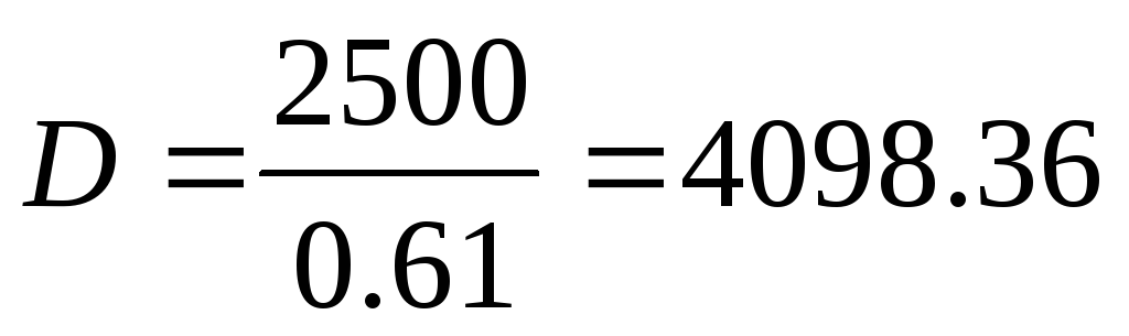
The center of magnitude is determined by the approximate formula:

Thus we accept 
Displacement is calculated using the following mass equation:
D– the required displacement of the vessel.

 - weight meter for the equipped body;
 - displacement mass meter;
 - speed of the vessel when fully loaded in calm, deep water;
 - Admiralty coefficient;
 - weight meter for mechanisms (power plant);
 - coefficient taking into account additional fuel, oil, feed water;
 - sea reserve coefficient;
 - specific fuel consumption;
 - autonomy; hour.
 - load capacity;
 - crew weight;
DW – deadweight;
 - mass of variable liquid cargo.
The mass meter of the equipped body is calculated according to the prototype: project 17310.
 ,
,
 .
.
Density of sea water - 
 ;
;
Estimated length, L– 93.5 m;
Width, B– 13.4 m;
Draft, T– 4.6 m;
The body weight of the equipped prototype is:  T.
T.
 .
.
The displacement reserve mass meter at this design stage is assumed to be in the range from 0.01 to 0.025. Let's accept  .
.
Let's calculate the coefficient A from the mass equation:
Coefficient IN:

Admiralty coefficient Ca calculated using the prototype formula:

Prototype speed  = 11 knots. Prototype speed data is given at draft T= 4.6 m.
Main engine power is Ne= 1740 kW.

The mechanism mass meter is equal to (the mass of the prototype mechanisms is  T)
T)

The coefficients of additional fuel and sea reserve are assumed to be equal:

Specific fuel consumption is:

Vessel autonomy in hours t is equal to:

Mass equation coefficient B equal to:
The mass of the crew and supplies is:
 - crew weight;
 - mass of provisions;
 - mass of fresh water;
 - mass of food and solid waste.
Crew weight: t.
 - number of crew members,
Weight of provisions: t.
A- autonomy (days), A=15
Mass of fresh water: t.
Mass of food and solid waste: t.
The mass of sewage and sub-sludge waters is equal to:
Mass equation coefficient WITH equal to:
The mass equation of the designed vessel is presented in the form:
We find the solution to the equation iteratively using the formula:

D= 4350 t.
To control the found displacement, we check the displacement using utilization coefficients.


 T.
T.
The difference in determining displacement by the two methods is 5%.
For further calculations, the displacement is taken D = 4350 t.
2.2 Determination of the main dimensions as a first approximation
The main dimensions to a first approximation are calculated using the buoyancy equation
 , Where

 - density of sea water;
 - displacement completeness coefficient;
L, B, T– length, width and draft of the vessel according to the waterline
To solve this equation, you need to set additional parameters:  , which to a first approximation we accept as the same as that of the prototype.


Then the draft of the vessel will be determined by the formula:
 m.
m.
The width of the vessel is:  m
m
The length of the vessel is:  m
m
The side height of the designed vessel is calculated by the formula: 

The ratio of the main dimensions of the vessel, if possible for the first limited navigation area, should not go beyond:
 ;
;


Let's check the coefficient of displacement completeness according to the speed limit of the vessel.

The full displacement coefficient for dry cargo ships must be within the range 
Since the coefficient of complete displacement falls within the recommended range, then for further design we accept δ= 0.835
For further calculations, the width of the vessel is assumed to be: B = 12.8 m.
Taking into account rounding, the length of the designed vessel is assumed to be equal to:

 m.
m.
Actual freeboard height of the vessel m.
The minimum possible freeboard height is  m.
m.
The side height complies with the load line regulations regarding freeboard height.
affects propulsion, stability, unsinkability, carrying capacity, cargo capacity, but chosen from the condition of reducing resistance to the movement of the vessel (from hydromechanical considerations).
R/D 
Figure 8 – Curve of the dependence of the resistance to the movement of the vessel on the overall fullness coefficient d
At δ cr
· Speed increases sharply ® main engine power and fuel mass increase
R®N® main engine power, fuel weight
· But the weight of the hull is reduced, the technology is simplified, the holds are more convenient (box shape)
Therefore, they try to take δ close to δ cr.
The magnitude of the drop in speed of the vessel in rough seas depends on the fullness of the vessel and its size. The larger the vessel, the less its fullness affects the magnitude of this drop in speed. Therefore, higher values of δ can be taken for large ships.
δ = a – b* Fr
where a and b are numerical coefficients depending on the type of vessel.
Table 10 Calculation formulas for determining δ
| Vessel type | Fr | Calculation formulas | Notes |
| Universal bulk carriers | 0,19-0,25 | δ = 1.07 – 1.68 Fr | |
| 0,25-0,29 | δ = 1.21 – 2.30 Fr | ||
| Tankers, bulk carriers | - | 0.03-0.05 more than dry cargo ships | Large dimensions, moderate speeds, a large proportion of ballast passages - the average value of δ for a round trip is less than with the design displacement at full load. In addition, δ allows ¯ main dimensions (T fully loaded), which is desirable for large vessels |
| Passenger ships, ferries | 0,25-0,33 | δ = 0.77 – 0.78 Fr | It is desirable to increase the main dimensions (primarily L and B) for the placement of premises (cabins, public spaces, etc.) ®¯ δ |
| 0,30-0,40 | δ = 0.40 Fr | ||
| 0,40-0,60 | δ = 0.50 |
The coefficient of completeness of the mid-frame area already fixed if selected δ And j. However, when choosing it, you must keep in mind the following circumstances.
For relatively slow and medium-speed vessels(Fr<0,30)b take as much as possible to sharpen the ends of full vessels (reduce drag). Upper limit ( b=1) limited to the possibility of constructing a theoretical drawing without noticeable breaks in the waterline at the boundaries of the cylindrical insert.
For determining b The following expressions can be used:
At δ <0,650 b =0,813 + 0,267 δ ;
At 0.615< δ <0,800 b =0,928 + 0,080 δ ;
At δ > 0,800 b =0,992.
For less complete relatively high-speed vessels, for which there is no reason for special sharpening of the extremities, the following values are recommended b :
Table 11 Values b for relatively high-speed vessels (Fr > 0,30)
| Fr | 0,34 | 0,38 | 0,41 | 0,46 | 0,50 |
| b | 0,925 | 0,875 | 0,825 | 0,800 | 0,790 |
|
Structural waterline area completeness coefficient(KVL) mainly affects the stability, unsinkability and cargo capacity of ships. At the same time, it is geometrically related to the shape of the frames, the sharpening angles of the vertical line and the coefficients δ And j. Therefore, it is initially accepted depending on these coefficients, then refined when developing a theoretical drawing.
For ships with U-shaped and V-shaped frames the following ratios can be used:
a = δ + 0.10 and a = δ = 0.12 respectively.
 (1 ratings, on average: 5,00 out of 5)